Reactor and Set Up
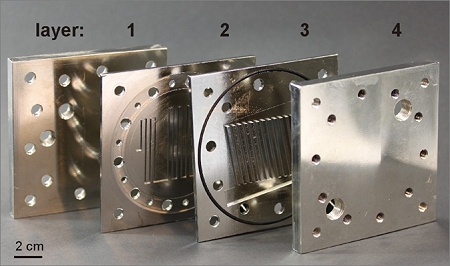
The mini reactor was constructed out of four copper blocks. All channels and holes were drilled mechanically. The plate #1 is for connecting the in- and outlets for the substrates and products. Plate #2 is the reactor and sensor plate, containing the 1 mm reaction channels and channels for temperature sensors. The next plate is on the one hand for sealing the reaction channels and on the other hand for the cooling channels. The plate #4 is for connecting the in- and outlets for the cooling liquid. All surfaces were nickel coated, because of the just limited resistance of copper against fluorine. The reactor was designed for slug flow. The flow parameters like slug and bubble length in relation to gas and liquid flow were measured in experimental series using only nitrogen. The channel length available for reaction is 38 cm.

Cyclic system
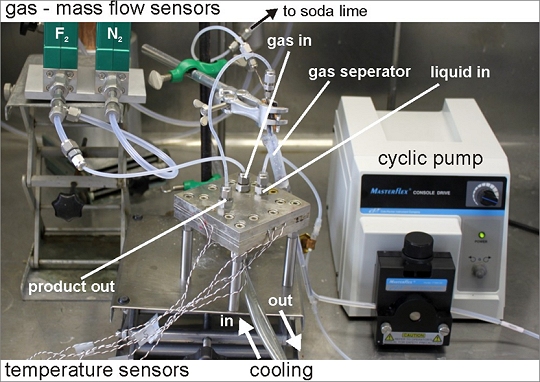
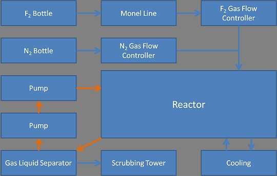
After the first experiments it became obvious that a cyclically piping of the liquid was necessary. The degree of fluorination was not sufficient by passing once through the reactor because of the huge difference of density between gases and liquid. For this reason a peristaltic pump (Masterflex L/T, Cole-Parmer, USA) with PFA tubes was integrated. This pump was chosen for reasons of demands regarding chemical stability, low flows and robustness. The set up is shown in the in the picture and scheme below. By letting the liquid pass the reactor several times, our system changed to a kind of batch system, which could be model system for more advanced reactors with more gas inlets or for several reactors in series.


